Any measuring equipment can become defective for a variety of reasons. Dial gauges may show faulty readings due to incorrect settings or slipped teeth.
The Dial IIndicators’ working principle is that the movement of the spindle is multiplied by the reading of the main scale due to the indication of the needle. A dial gauge or indicator estimates the distance between two plates. The best way to rectify the wrong readings and get accurate figures is to calibrate the indicator.

What is the dial indicator?
A dial indicator, also known as a dial test indicator or plunger dial indicator, is a precision measuring tool used to measure small distances and deviations in mechanical systems. It is typically used in manufacturing, mechanical engineering, and machine maintenance to ensure that machines are functioning correctly and within tolerance.
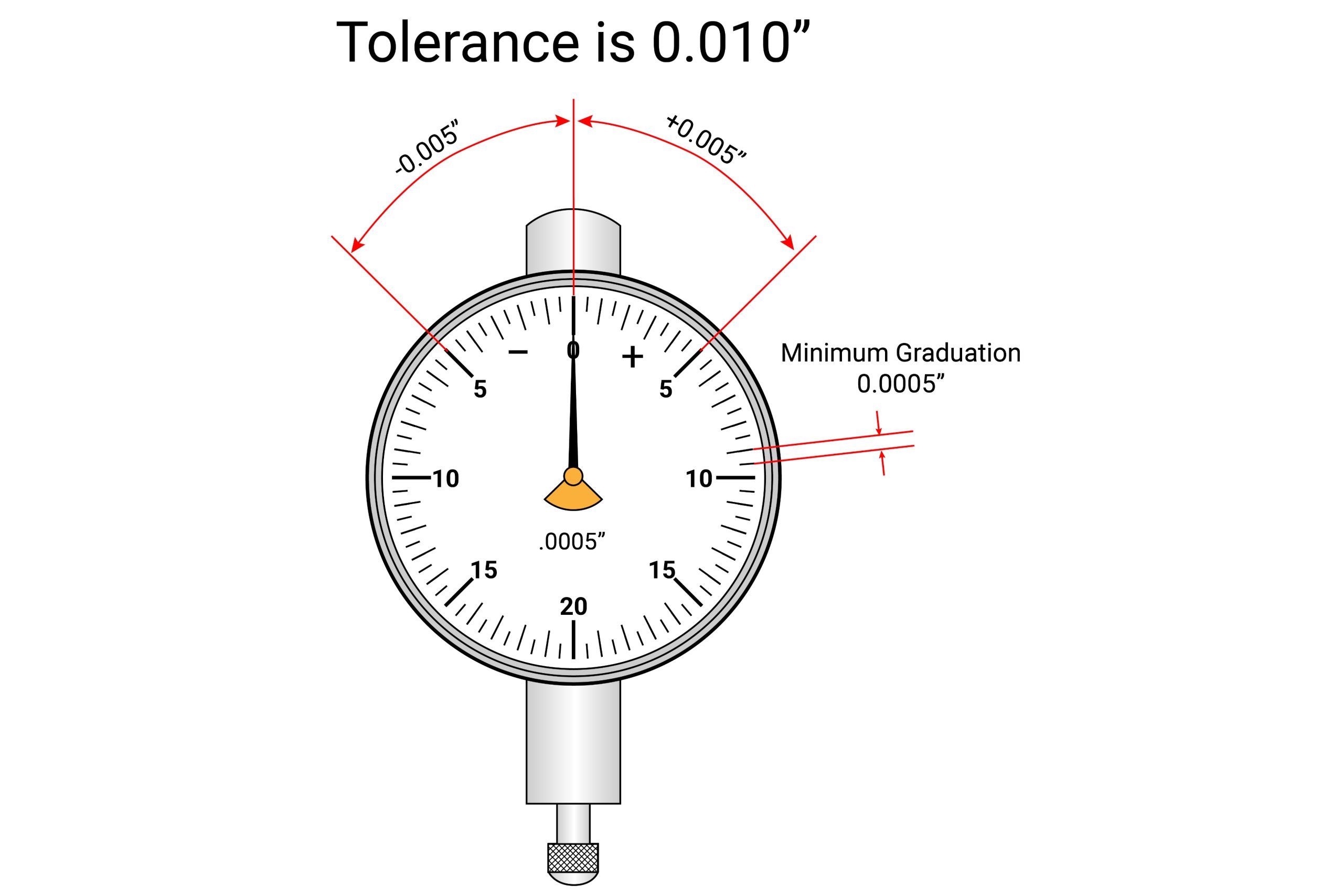
A dial indicator consists of a dial face with a needle that moves in response to changes in the position of a plunger or probe. The plunger is typically attached to a mounting device that can be adjusted to different positions and angles to measure other machine parts.
To use a dial indicator, the plunger is placed in contact with the part of the machine being measured, and the dial face is zeroed out to establish a reference point. As the machine is adjusted or moved, the plunger moves in response, and the needle on the dial face indicates the distance and direction of the movement.
Dial indicators come in various sizes and accuracies, with some models capable of measuring distances as small as 0.001 inches (0.0254 mm). They are often combined with other measuring tools, such as micrometers and calipers, to ensure accurate and precise measurements.
Dial Indicator Calibration Procedure
Here are the step-by-step bullet points for a typical dial indicator calibration procedure:
- Gather the necessary equipment: To calibrate a dial indicator, you will need a calibration standard, a mounting device (such as a magnetic base), and a precision measuring instrument (such as a micrometer or caliper).
- Establish a reference point: Set the dial indicator to retract the plunger or ” ero.” Secure the indicator in place with the mounting device.
- Measure the calibration standard: Use the precision measuring instrument to measure the calibration standard at several points along its length. Record the measurements for each issue.
- Test the dial indicator: Place the calibration standard against the dial indicator’s plunger and adjust the mounting device until the plunger is in contact with the standard. Take a reading on the dial indicator and compare it to the calibration standard’s known measurements. Record any discrepancies.
- Adjust the dial indicator: If the dial indicator is not reading accurately, use the adjustment screw or other mechanism on the indicator to align it with the calibration standard. Repeat the testing process until the dial indicator is reading accurately.
- Verify the calibration: Once the dial indicator reads accurately, retest it on the calibration standard at several points to ensure it remains accurate throughout its range. Record the measurements for each moment.
- Document the calibration: Document the calibration process and results, including the calibration date, the technician who performed the calibration, the equipment used, and any adjustments made to the dial indicator. Store the documentation in a safe and easily accessible location.
- Repeat the calibration: To ensure accuracy over time, calibrate the dial indicator regularly according to your oorganization’squality management system or industry standards.
Given below are the detailed steps of the plunger dial gauge calibration procedure:
Practical example:
- Firstly, clean off the dirt and debris from the gauge blocks, surface plate, and the pplunger’stip.
- Then, lock the indicator on the stand so that it rests adequately high so that the plunger can move to its complete length and stay in position to touch the surface plate.
- Place the pplunger’stip on the surface plate. Then, spin the iindicator’sface until the ‘’’’ marking lines up with the dial.
- Lift the plunger and then slide the 0.020-inch gauge block beneath it.
- Keep the plunger on the gauge block’s surface. Ensure that the indicator displays the reading as ‘’.020-inch.’’ Lift and place the plunger repeatedly to check twice that the gauge shows the same task simultaneously.
- Repeat the same with 1-inch, 0.400-inch, 0.250-inch, 0.100-inch, 0.050-inch, and 0.025-inch blocks. Examine every block at least three times for the iindicator’sreading.
If the plunger is at a 2-inch depth, pile up the blocks to verify the iindicator’sreading at 2-inch, 1.400-inch, 1.250-inch, 1.100-inch, 1.050-inch, and 1.025-inch increments.
You must reject the indicator if the readings deviate by an increment of over ‘’’’ across the initial 2-1/3 dial revolutions. Thereon, shift the task by one increment for every complete dial rotation. Besides, you need to adjust the relevant offset value by mental calculations while taking the readings.
Note:
The dial gauge must be calibrated daily if you seldom use the device. If you use a dial gauge at your workplace, you may follow the standard tooling procedures available at the facility.


